PHOTON RT UV-VIS-MWIR Spectrophotometer

PHOTON RT UV-VIS-MWIR Spectrophotometers for Coaters
PHOTON RT UV-VIS-MWIR SPECTROPHOTOMETER
Designed for precision. Built for performance.
PHOTON RT is the world’s only spectrophotometer purpose-built for true optical coating metrology — enabling meaningful, traceable characterization of coatings under field-like operating conditions. It uniquely combines broadband polarization control and variable-angle measurements across an unmatched UV–MWIR range (220–5200 nm), providing deep insight into the real-world performance of multilayer thin-film optics.
Designed for fully automated spectral analysis of transmission and absolute reflectance, PHOTON RT supports advanced qualification of coated optics — flats, prisms, gratings, and complex optical assemblies.
The system is available in three configurations, covering wavelengths from 185 nm to 5200 nm.

KEY ADVANTAGES:
- Broad Wavelength Coverage — measure coatings and components across UV–MWIR in a single system (185–5200 nm), reducing instrument swaps and simplifying process integration.
- Seamless Spectral Stitching — continuous, gap-free spectra across grating and detector transitions, eliminating the step-changes commonly seen in other instruments.
- Integrated Beam Tracking — a uniquely automated approach that corrects beam offset at non-normal AOI, preserving true spot positioning and data integrity, and supporting characterization of multi-element prisms.
- Absolute %T/%R Accuracy — direct measurements without reference samples reduce uncertainty and improve traceability in coating qualification.
- Variable-Angle and Polarization-Resolved Metrology — evaluate coating behavior under realistic geometries in batch measurements involving clear separation of S and P states even at steep AOI.
- High Stability and Baseline Retention — long-term measurement repeatability supports routine production use and reduces recalibration overhead.
- Minimized Human Error – automated procedures ensure consistent, reproducible result
- Application-Centric Design — from full automation to a smooth, silent lid mechanism, every detail enhances ergonomics and stability for daily intensive use in labs and on the production floor.
The PHOTON RT spectrophotometer sets a new standard in coating metrology, delivering unmatched accuracy, efficiency, and reliability to meet the most demanding optical coating requirements.
PHOTON RT Multifunctional Spectrophotometer. Technical Specifications
|
PHOTON RT Spectrophotometer. |
||||||
|---|---|---|---|---|---|---|
| MODEL | 0217 | 0226 | 0252 | |||
| OPTICAL CONFIGURATION | ||||||
| Photometric functions | %T, %R | |||||
| Effective wavelength range, nm | 185–1700 | 185–2600 | 185–5200 | |||
| Built-in polarizer, nm | 220–1700 | 220–2600 | 220–5200 | |||
| Optical scheme of monochromator | Czerny–Turner | |||||
| Optics | Mirror, MgF2 | |||||
| Reference channel | Yes | |||||
| Wavelength sampling pitch, nm | 0.25–100 | |||||
| Spot size on the measured sample, mm | 6 x 2 → 2 x 2 | |||||
| Turning pitch angle of sample stage | 0.01° | |||||
| Turning pitch angle of photodetectors | 0.01° | |||||
| Beam displacement compensation | -60.0 mm ... 0 ... +60.0 mm (actual value depends on detector position) |
|||||
| Variable angle measurements |
1. 0–75° for transmittance (up to 85° with 7085 sample stage) |
|||||
| Wavelength subranges, nm | Ultimate spectral resolution, nm (non-polarized light) | Wavelength accuracy, nm | Wavelength repeat accuracy, nm | |||
| 185–990 nm | 0.6 | ±0.5 | ±0.25 | |||
| 990–1700 / 2450 / 2600 nm | 1.2 | ±1.0 | ±0.5 | |||
| 2450–5200 nm | 2.4 | ±2.0 | ±1.0 | |||
| Stray light level, % at 532 nm | ˂ 0.1 | |||||
| Angle of beam divergence | ±1.6° | |||||
|
Photometric accuracy (VIS–NIR range) |
(VIS–NIR) ±0.0045 Abs (1 Abs); ±0.0025 Abs (0,33 Abs); ±0.0058 Abs (1.5 Abs) |
|||||
|
Photometric repeat accuracy (VIS–NIR range) Determined using 0,1 second accumulation, maximum deviation for 10 subsequent measurements |
(VIS–NIR) 0.0004 Abs (1 Abs); 0.0001 Abs (0,33 Abs); 0.005 Abs (1.5 Abs) |
|||||
| Stability of baseline, %/hour (VIS range) | ˂ 0.1 (one hour warm-up time) | |||||
| Unattended polarization measurements with built-in polarizers |
S, P, (S + P) / 2 |
|||||
| Zero order / Green beam | Built-in, automatic | |||||
| Light sources, preinstalled |
1. Deuterium lamp: 1 ea |
|||||
| Light sources, spare | Halogen lamp: 2 ea (included with shipment). Other spare light sources can be ordered additionally |
|||||
| SAMPLE COMPARTMENT | ||||||
| Dovetail baseplate for sample stages | Designed for mounting of motorized and non-motorized sample stages. Integrated controller ensures instant detection of the motorized stage | |||||
| Planar sample stage |
For measurement of transmission and reflection of planar samples with size greater than 12.0 x 10.0 mm |
|||||
| Independent positioning |
Independent computer controlled positioning of sample stage and photodetectors unit |
|||||
| Synchronized positioning | Synchronized computer controlled positioning of sample stage and photodetectors unit depending on the selected photometric function | |||||
| Size of samples |
Min. 12.0 x 10.0 mm - for measurement at 0–10° incidence angles Min. 12.0 x 25.0 mm - for measurement at 10–75° incidence angles Max. sample size:
|
|||||
| Sample stage for PBS cubes | 50.0 x 50.0 x 50.0 mm sample stage with two additional cube holders 1" x 1" x 1" and 1/2" x 1/2" x 1/2" | |||||
| Optional motorized and non-motorized sample stage |
1. MP Stage. Multiple sample measurement |
|||||
| INTERFACE, DIMENSIONS AND WEIGHT | ||||||
| Interface | USB 2.0, Windows-based, English | |||||
| File saving formats | res (txt), xls, pdf, csv | |||||
| Power consumption, Watt | 110 | |||||
| Power input | 110–220 V (±10 %), 50–60 Hz | |||||
| Width х Depth х Height, mm (inches) | 425 x 625 x 285 (16 3/4" x 24 2/3" x 10 1/5") | |||||
| Net weight, kg (lbs) | 50 (110) | |||||
Values are measured after 60 minutes warm-up time
The information provided represents typical product specifications and is subject to change without prior notice. Actual specifications may vary for individual units.
High-reflectivity laser coatings are among the most demanding optical elements in terms of measurement accuracy. At oblique angles of incidence, their performance becomes strongly polarization-dependent, requiring precise separation and independent evaluation of S- and P-polarized components.
The example shown illustrates absolute reflectance measurements of a broadband laser mirror at 45° angle of incidence, performed for both S and P polarizations. The coating exhibits near-unity reflectance across the working spectral range, placing stringent requirements on photometric accuracy, polarization purity, and system stability.

PHOTON RT enables:
- Accurate measurement of reflectance levels approaching 100%
- Clear and reliable separation of S and P polarization components
- Detection of subtle spectral differences between polarizations
- Artifact-free stitching of gratings and detectors, ensuring smooth and physically consistent spectra
The zoomed-in view demonstrates the absence of stitching artifacts typically observed in conventional spectrophotometers when switching between spectral ranges. This is particularly important in high-reflectance regions, where even minor distortions may lead to incorrect interpretation of coating performance.

In addition to fixed-angle measurements, PHOTON RT allows seamless characterization over a wide angular range (0° to 75° AOI, and up to 85° with dedicated 7085 stage), enabling realistic simulation of operating conditions in laser systems and optical assemblies.
Laser-based measurement techniques are widely used for evaluating ultra-low-loss coatings, particularly at selected wavelengths where extreme sensitivity is required. PHOTON RT complements these approaches by providing broadband, angle-resolved and polarization-resolved measurements in a fully automated and reproducible manner, revealing critical aspects of coating behavior that remain inaccessible to conventional laser-based techniques.
This enables a more complete and application-relevant understanding of coating performance, especially in systems where angular dependence and polarization effects are critical.
PHOTON RT spectrophotometers are renowned on the market for their exceptionally low noise levels. Our latest product configurations feature ultra-low noise across the entire range from 185 nm in the ultraviolet to 2500 nm in the mid-spectrum. The results below demonstrate the noise verification and high baseline stability over a 14-hour continuous test period. Following one baseline calibration, 76 consecutive measurements were performed.
The high-performance PhotonRT spectrophotometer delivere top-quality results for the most complex and cutting-edge optical coating measurements.
.png)
One of the truly unique features of PHOTON RT spectrophotometer is the capability to run broadband measurements. The most sophisticated configuration offers an unsurpassed opportunity to qualify optical coatings for 185 - 5200 nm.
Throughout our business history, we regularly set new benchmarks for broadband measurement capability. Since our first announcement of 380 - 2500 nm configuration of PHOTON RT many years ago, we have persistently looked for technical solutions, developed new technologies, and conducted tests to expand the spectral range of the instrument. Each new milestone we reached was a new challenge for our team. Each new frontier required more unique solutions.
Many of our customers consider PHOTON RT a product-of-choice for coaters, especially for its world-record broadband measurement capability.
Shown below is an example of single-run broadband absolute specular reflectance measurement of Au mirror. Layer thickness exceeds 50 nm. Standard product settings were used.

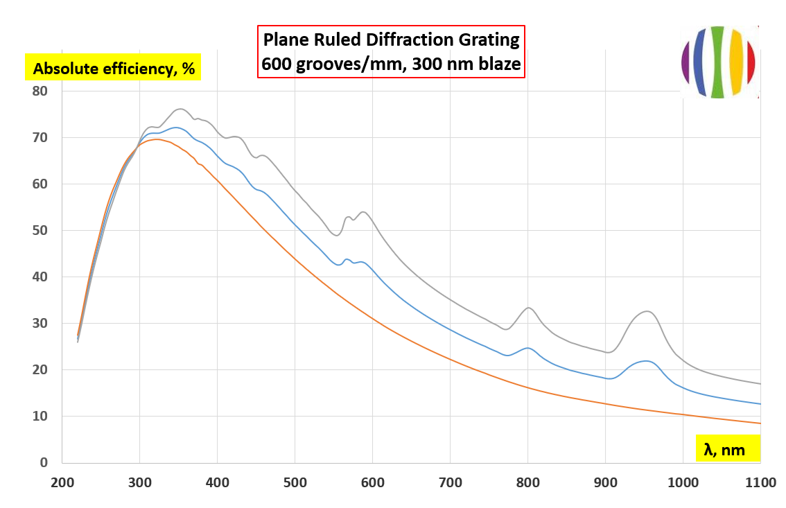
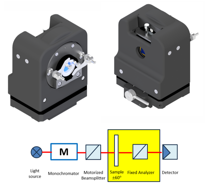
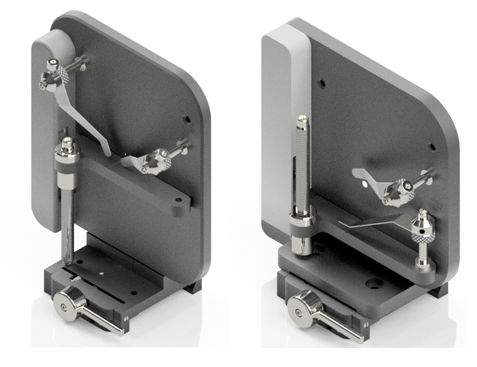
The PHOTON RT spectrophotometer can be supplied with an optional software package designed for automated measurements of the spectral efficiency of diffraction gratings.
The principle behind the technology is fully aligned with the real-world performance and application of diffraction gratings. The instrument enables automated spectral measurements of both reflective and transmissive gratings, in monochromator and spectrometer setup. It accurately determines diffraction efficiency and polarization response for grating area ranging from 5 mm² to nearly 120 mm², depending on the angle of incidence (AOI) and grating type.
The instrument features precise motion control and dedicated software to adjust the grating angle of incidence. It performs synchronized scans of angle and wavelength to rapidly acquire diffraction efficiency in the selected diffracted order. Additionally, the motorized detector scans through a range of angles and wavelengths, calculated according to groove density.
As a result, this technology provides a reliable solution for qualifying both reflective and transmissive diffraction gratings from UV to MWIR.
The following types of gratings can be measured:
Types: Plane/Concave, Reflective/Transmissive, Ruled/Holographic.
Minimum size of the grating area: 5,0 mm x 5,0 mm
Maximum sample height: 120 mm
Wavelength range: 185 nm - 2600 nm, 220 nm - 5200 nm
Incident angle range: 8,0 deg - 75,0 deg
Below is an example of spectral efficiency data for a plane-ruled reflection grating:
600 grooves/mm, 300 nm blaze wavelength, 8° AOI, diffraction order -1.
The results were obtained in a fully automated mode, eliminating the need for manual adjustments to the grating or detector by an optical engineer.
Modern optical coatings often operate at high angles of incidence (AOI) thus offering unique features to photonics devices. A typical high angle is 45 degree, or Brewster angle. Polarizing coatings are also specified for operation at 72 deg AOI for growing number of applications. This measurement need is already met with our standard PHOTON RT configuration both for transmission and reflection.
A few of our customers have recently inquired if we can develop a solution to measure coatings at extreme angles of incidence, like 80 or 85 degrees. Under this challenging specification, the beam travels very close to the substrate’s surface, so the beam projection expands dramatically. Additionally, the full beam energy must enter the substrate and reach the detector both in transmission or reflection mode, without any losses. Finally, S and P polarization states shall be clearly defined, separated and measured.
Jointly with one of our customers, EssentOptics engineers developed a separate sample stage for measurement of transmission and reflection seamlessly from 70 up to 85 deg AOI.
Images below show our “7085” sample stage with a test sample installed and measurements results of transmission and reflection at 8, 70 and 85 deg AOI, including S and P polarizations. We used a broadband high reflection mirror to demonstrate measurement capabilities using the “7085” stage. These results demonstrate that even measurements at extreme angles of incidence can be successfully performed using the PHOTON RT spectrophotometer.


Measurements of UV optical coatings are often needed across the photonics industry. Wide range of UV coatings has been developed for various applications:
- UV-Enhanced aluminum mirrors and multilayer UV mirrors are used in lasers and other types of optical systems for beam steering or reflecting needs. They operate at different AOI ranging from 0 deg to 45 deg, observing also polarization requirements. Typical applications of UV mirrors include UV-curing-machines, UV-exposure machines, disinfection systems, medical instruments, sensor filters and other setups where ultraviolet heat / light separation is required.
- UV antireflective coatings increase transmission and enhance contrast. They also reduces scattered light in imaging devices and second-surface reflections of beamsplitters
- UV beamsplitters, UV notch filters and UV narrowband/wideband filters are designed for low power applications and can be found in many research and industrial installations.
The following specific performance features of metrology-grade spectrophotometers are the essential prerequisites to enable meaningful UV measurements:
- low noise / high stability baseline
- low internal noise of the instrument
- low stray light.
The combination of these factors effectively increases the quality level of the measurement results. PHOTON RT spectrophotometer is designed to meet the above critical criteria as standard.
PHOTON RT: Low noise / high stability baseline (UV range)
Test procedure: 14 consecutive measurements during one hour

PHOTON RT: Low internal noise of the instrument (UV range)
Test procedure: Transmission measurement with fully blocked measurement channel

PHOTON RT: Low stray light (UV range)
Test procedure: Transmission measurement of borosilicate glass with no transmission in UV

Shown below are examples of UV mirrors and UV AR coatings measured with PHOTON RT spectrophotometer. Standard product settings with no smoothing were used for all tests.
Example 1: UV mirror optimized for 193 nm

Example 2: UV mirror optimized for 340 nm. S/P Reflectace @ 30, 45, 60 deg AOI

Example 3: UV AR coating optimized for 203 nm

Beamsplitter cubes are optical components used to separate a light into two beams (sometimes three beams, like X-cubes or RGB-cubes) at a designated T/R ratio. The cube consists of two cemented right-angle prisms typically with a multilayer interference coating on the internal hypotenuse, and all other four faces are AR coated to reduce losses due to reflection. Beamsplitter cubes can be premounted or unmounted.
Beamsplitter cubes can be non-polarizing (dichroic), polarizing or intensity splitters.
- Non-polarizing or dichroic beamsplitters are designed to split incident light by its wavelength
- Intensity beamsplitters are used when the incident light needs to be separated by a pre-defined ratio regardless to the polarization state light's wavelength
- Polarizing cube beamsplitters are designed to split incident light into its polarized components rather than by simple transmission and reflection. The quality of the polarized cube is typically defined by the extent and accurate beam deviation of the transmitted and reflected polarized light and by the extinction ratio of the cube.
Traditionally the cubes were measured at normal angle of incidence. However, new photonic instruments utilize advance designs where beamsplitters can occasionally or specifically operate at variable AOI’s (augmented reality devices, optical computers, next generation projecting systems etc).
Virtually any beamsplitter cubes can be successfully measured with PHOTON RT spectrophotometer at normal or variable AOI’s. Below are a few amazing examples showing capabilities of PHOTON RT spectrophotometer.
Example 1
S-pol and P-pol transmission and absolute reflection measurement of a miniature polarizing cube (just 5,0 x 5,0 mm size) at normal AOI and also negative/positive AOI's. The max AOI we reached was 22 deg.

![]()
.png)
Example 2
S-pol and P-pol transmission measurement of 1” cube at +20 / -20 deg AOI with 1 deg step
.png)
Example 3
S-pol and P-pol transmission and absolute reflection measurement of the X-cube.
.png)
Although there is no “standard” samples size, typically our customers use 1 inch samples for witness pieces or samples with 10,0 mm diameter and bigger for commercial applications.
However, there are plenty of applications with smaller size samples, like 5,0, 4,0 and even 3,0 mm diameter. Engineers usually face a problem of measuring such samples. Traditionally they use witness pieces to assess transmission or reflection. These pieces are placed either in the test slide changer or in the close proximity to the commercial samples located on the calotte. Depending on the uniformity level achieved in the vacuum chamber, the coating on the commercial sample can have certain degree of mismatch with that on the witness piece.
We have received a number of requests to find a solution to measure small samples. As a result of our R&D we have provided our customers with a few different attachments that reduce the spot size on the sample. However, the use of them is associated with extra engineer’s time for careful alignment of the fixture and the sample. The solutions are not also perfect when the engineer has different samples in the batch and needs to measure them sequentially.
Engineers at EssentOptics were puzzled with this problem for a number of years. Several brainstorming sessions have eventually led to a breakthrough design changes in the PHOTON RT spectrophotometer. The new design of motorized slits now enables our customers to change the spot height smoothly from almost 6,0 x 2,0 mm to 2,0 x 2,0 mm with just a click of a button. The engineer can set the desired slit size to meet the actual clear aperture of the sample. Video below demonstrates the process of changing the spot size on the sample with PHOTON RT spectrophotometer.
 Application:
Transmission and reflection measurements at 0–75° AOI
* Included in the basic delivery set
Features:
- Measurement of planar samples
- Transmission / Reflection
- Variable AOI: up to 75°
Ordering:
P/N 048.010.000
.png)
Application:
For measurement of transmission and reflection of prisms
* Included in the basic delivery set
Features:
- Transmission / Reflection
- Variable AOI
Ordering:
1. Stage base: P/N 048.027.000
2. Inserts:
- 1": P/N 033.016.108
- 1/2": P/N 033.016.110
- Inserts for prisms measurement of other shapes and sizes are available on request
 Application:
- Sequential baseline calibration and automated transmission measurements of multiple samples without opening the lid
- Variable-angle and polarization-dependent transmittance measurements
Features:
- Transmission
- Variable AOI up to 45°
- Measurements of reflection are not specified
Ordering:
1. Stage base: P/N 048.038.000
2. Multiposition wheel:
Metric
- 30.0 mm x 10 pos: P/N 048.038.660
- 25.0 mm x 10 pos: P/N 048.038.640
- 12.5 mm x 20 pos: P/N 048.038.610
Imperial
- 1" x 10 pos: P/N 048.038.650
- 1/2" x 20 pos: P/N 048.038.620
 Application:
Measurement of transmittance and absolute specular reflectance from different areas of a sample (sample mapping), including polarization- dependent and angular-dependent measurements up to 45° angle of incidence (AOI)
Features:
- X range: ±25.0 mm
- Y range: ±20.0 mm
- Mapping area: 50.0 x 40.0 mm
- Max sample size: 114.0 x 91.0 mm
- Min sample size: 55.0 x 45.0 mm
- Transmission / Reflection
- Variable AOI up to 45°
Ordering:
P/N 048.028.100
 Application:
Transmittance measurement at different areas of the sample (sample mapping) at AOI up to 10°.
Features:
- X range: ±55.0 mm
- Y range: ±20.0 mm
- Mapping area: 110.0 х 40.0 mm
- Max sample size: 180.0 x 91.0 mm
- Min sample size: 115.0 x 45.0 mm
- Transmission
- Variable AOI up to 10°
Ordering:
P/N 048.028.200
 Application:
Precision transmission measurement and automated zone mapping of multi-zone bandpass filters at normal incidence using a defined narrow aperture.
Features:
- 0.3 mm width of the beam spot
- Width of individual filter zone down to 0.7 mm
- Measurement step down to 0.1 mm
- Maximum coated filter area (X–Y): 50.0 x 40.0 mm
- Computer-controlled zone detection, zone centering / measurement, filter mapping.
Ordering:
1. Stage base: P/N 048.041.000
2. Filter holders are custom designed

![]()
 Application:
Combined variation of AOI and azimuthal sample orientation for transmission and reflection measurements. Enables angular characterization at fixed AOI with different azimuthal orientations, or full two-dimensional angular analysis of optical components
Features:
- Features 0–360° sample rotation along beam axis
- Max sample size: 70.0 mm diameter
- Min sample size: 25.0 mm diameter
- Transmission / Reflection.
- Variable AOI up to 60°
Ordering:
P/N 048.034.000
.png) Application:
Application:
Polarization-resolved transmission measurements at normal incidence using a rotating analyzer for prism-based optical assemblies (RA Stage) and flats (RA2 Stage).
Enables evaluation of polarization-dependent transmission and phase shift characteristics.
Features:
- Spectral range: 220–2600 nm
- Analyzer rotation about the beam axis: 0–360°
- Analyzer angular pitch: 0.1°
- Maximum sample size: 38.1 mm prism*
- Minimum sample size: 12.7 mm prism*
- Measurement capabilities: Transmission (only)
Ordering:
1. RA Stage (prisms): P/N 048.048.100
2. RA2 Stage (flats): P/N 048.048.200
* Inserts for different prism sizes are required. Contact the manufacturer for further support.
 Application:
Polarization-dependent transmission measurements of birefringent optical elements
Features:
- Sample diameter: 0.5”, 1”
- Rotation angle of the sample along beam axis: ±45°
- Scan step for wave plate rotation angle: 0.1–5.0°
- Tilt angle of the sample to beam axis: 3°
- Selection of built-in analyzers UV–VIS–MWIR
Ordering:
1. QW-Stage, motorized (220–2200 nm analyzer): P/N 048.035.510
2. QW-Stage, motorized (380–2200 nm analyzer): P/N 048.035.520
 Application:
Unattended baseline calibration and measurement without opening the lid. Especially suitable for nitrogen-purged measurements
Features:
- Transmission / Reflection
- Variable AOI up to 75°
Ordering:
P/N 048.032.000
 Application:
Characterization of coatings using a small beam spot
Features:
- Integrated aperture ensures a small beam spot on the sample: Æ 1.0 mm or Æ 3.0 mm
- Primarily intended for normal-incidence transmission measurements with a controlled small beam spot
- For angled measurements, identical geometry must be maintained between baseline and sample measurements to ensure valid results
Ordering:
1. P/N 048.043.200 (Æ 3.0 mm aperture)
2. P/N 048.043.300 (Æ 1.0 mm aperture)
Application:
Primary: Transmission and reflection measurements at 70–85° AOI
Secondary: Transmission and reflection measurements at 0–30° AOI
Features:
- Transmission / Reflection
- Variable AOI up to 70–85°
Ordering:
P/N 048.033.000
Other products of our company

PHOTON RT 0420 Ultra Spectrophotometer
High-performance spectrophotometer for VIS-SWIR transmission measurement of ultra-narrow bandpass filters, edge filters with extremely steep slopes, notch filters, and coatings with high optical density

PHOTON RT 7514 LWIR Spectrophotometer
The PHOTON RT 7514 spectrophotometer is a unique dispersive-type instrument designed for LWIR (7,500 nm - 14,000 nm) transmission and reflection measurements of optical coatings. It operates at both normal and variable angles of incidence, supporting S- and P-polarization
LINZA 150 UV-VIS-NIR Spectrophotometer
LINZA 150 is the world only spectrophotometer designed for unattended measurement of transmittance and reflectance of lenses and multi-lens assemblies

LINZA 2752 MWIR Spectrophotometer
LINZA 2752 spectrophotometer is the most advanced soution for MWIR on-axis transmission measurement of lenses and fully assembled lens objectives.